Home » Applications » Variable frequency drive for centrifugal pump
Variable frequency drive for centrifugal pump
If you operate too far off the centrifugal pump's best efficiency point, the shaft will deflect radially and that could lead to both seal and bearing problems. So, what should you do if you have to vary the capacity of a centrifugal pump? The discharge control valve is not a logical choice because, if you alter the capacity of a centrifugal pump, the head changes also, and in most cases this will guarantee you'll be operating off the pump's best efficiency point. It turns out there are several possible solutions to preventing the problem of shaft deflection, while running off the centrifugal pump's best efficiency point.
For the VFD to be a sensible solution to your pumping application the system curve would have to fall on, or close to this best efficiency point line, or you will experience radial loads that will translate to shaft deflection. Most centrifugal pump companies want you to operate within 5% to 10% of the best efficiency point. Heavy duty pumps that have a low L3/D4 (shaft diameter to shaft length ratio) have a much larger operating window.
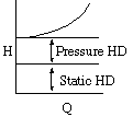
The above diagram shows that the head is going to have to increase at a predetermined rate as the capacity increases. There are three kinds of head that will have an affect on the centrifugal pump's capacity:
Lets take a look at a system curve for a typical boiler feed pump, or any pump that will be discharging into a constant pressure vessel or tank:
You will find this last curve in many common pumping applications:
One of the most common methods of varying pump shaft speed is to use a VFD. These VFDs take advantage of the fact that torque, speed and horsepower of an AC electric motor are related to the frequency and voltage of the electrical power supply. Here is the relationship:

Variable frequency drives convert incoming alternating current (AC) to direct current (DC) and then invert the DC power into variable frequencies and voltage AC power. Most variable frequency drives produce a constant voltage/frequency (hz)ratio.
A low L3/D4 shaft is still your best protection against damage caused by operating off the centrifugal pump's best efficiency point. Any pump that experiences frequent starts and stops has this problem.
If the dominate head in the system is pipe friction losses a variable speed device can have some advantages:
- Switch to a double volute pump design.
- Install a pump discharge bypass line back to the storage tank, such as the type commonly used on boiler feed pumps.
- Convert to a low L3/D4 pump design that will operate in a wide window.
- Install a support bushing in the end of the stuffing box, move the seal closer to the bearings and accept a small amount of shaft deflection.
- And the big question, "How about a variable frequency drive (VFD)"?
- A variable speed electric motor
- A gasoline or diesel engine.
- A variable pulley arrangement.
- A changeable gear box.
- Electrical switch gear
- A hydraulic coupling.
 |
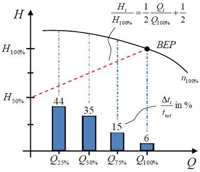
Changing the speed of a centrifugal pump has just about the same affect as changing the diameter of the pump impeller. The "Affinity Laws" allow you to predict the results of this change. The area within the curved lines (ABCD) is called the operating window of the centrifugal pump. Notice that the sloping best efficiency point line intersects the capacity leg (Q) at an angle. This slope causes a problem with many pumping applications. |
For the VFD to be a sensible solution to your pumping application the system curve would have to fall on, or close to this best efficiency point line, or you will experience radial loads that will translate to shaft deflection. Most centrifugal pump companies want you to operate within 5% to 10% of the best efficiency point. Heavy duty pumps that have a low L3/D4 (shaft diameter to shaft length ratio) have a much larger operating window.
The above diagram shows that the head is going to have to increase at a predetermined rate as the capacity increases. There are three kinds of head that will have an affect on the centrifugal pump's capacity:
- Static head. The distance from the discharge of the centrifugal pump center line to highest liquid level minus any distance caused by the siphon affect.
- Pressure head. The head caused by pumping into a pressurized vessel.
- System or friction head. The loss of head caused by friction in the piping, valves and fittings.
Lets take a look at a system curve for a typical boiler feed pump, or any pump that will be discharging into a constant pressure vessel or tank:
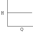 |
The boiler is running at a constant pressure, but the steam demand is changing. The boiler feed water capacity must vary with the steam demand, but the pressure or head must remain constant. The system curve is a straight horizontal line because the dominant head is the pressure head. The amount of piping and elevation is minimal. |
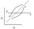 |
Laying the best efficiency point sloping line from a VFD on top of the system curve (EF) would show that we are at the best efficiency point only at one point. Allowing the tolerances of the operating window (ABCD) you can see that we are operating efficiently over only a portion of the desired system curve. A similar application would be pumping a varying capacity to a very high tower or elevation where the static head is the dominant head. |
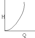 |
A hot or cold water circulating system describes a different type of system curve. The dominant head in this example is the friction head and that varies by almost the square of the capacity. In other words, two times the capacity gives you four times the head, or three times the capacity would give you nine times the head. If you plot this on a piece of chart paper you would get an "exponential curve" as shown on the left. |
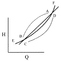 |
If you lay the best efficiency point line on this "exponential curve E-F" you would get a pretty good match and just about all of the system curve falls within the operating window (ABCD), so this becomes the ideal variable speed application. In other words you use a VFD any time the system head is dominated by friction in the piping, fittings and valves. |
You will find this last curve in many common pumping applications:
- Circulating hot or chill water systems.
- Loading liquid cargo or fuel to a ship from a distant tank farm.
- A piping system with many outlets and a varying demand for product.
- A fire hose.
 |
Many systems are a combination of all three types of heads. You're going to have to decide which head is the dominant one. |
One of the most common methods of varying pump shaft speed is to use a VFD. These VFDs take advantage of the fact that torque, speed and horsepower of an AC electric motor are related to the frequency and voltage of the electrical power supply. Here is the relationship:
- hz = frequency or number of cycles per minute. In the U.S we run 60 cycles per minute (hertz), most of the rest of the world uses 50 hertz.
- Torque capability = F(volts/hz)
Variable frequency drives convert incoming alternating current (AC) to direct current (DC) and then invert the DC power into variable frequencies and voltage AC power. Most variable frequency drives produce a constant voltage/frequency (hz)ratio.
A low L3/D4 shaft is still your best protection against damage caused by operating off the centrifugal pump's best efficiency point. Any pump that experiences frequent starts and stops has this problem.
If the dominate head in the system is pipe friction losses a variable speed device can have some advantages:
- They can deliver a broad range of head / capacity figures so your estimate of flow needs does not have to be exact.
- You can eliminate the need for a throttling valve. Valves can leak and they require maintenance.
- Often an inefficient bypass line can be eliminated.
-
Throttling a pump discharge produces unwanted heat in a pump that can be eliminated by changing the pump speed instead. This heat can cause the pumping fluid to:
- Vaporize or flash
- Crystallize
- Change viscosity
- Coke or build a film on sliding seal parts.
- Become more corrosive.
- The heat can also change critical dimensions causing lapped seal faces to go "out of flat".
- The fluid viscosity can change with speed if it is a non Newtonian fluid. As an example, the viscosity of dilatants increases with agitation requiring additional power.
- The shaft can hit a critical speed on its way to the ideal operating speed.
- You can dial in too much capacity that can, in turn, burn out the electric motor.
- Operating off the best efficiency point can cause shaft deflection.
- Explosion proof motors must be approved to operate over the entire operating range. At the lower rpms the cooling fan is often not rotating fast enough.
- Variable speed demands may affect the electrical power distribution system by reducing electrical demand.
- The mechanical seal has to be designed to operate over the entire speed range. At higher speeds the design has to be of the stationary type with the spring face load reduced.
- At higher shaft speeds the NPSH requirement is increased to prevent cavitation problems. You may have to install an inducer on the pump's impeller
- Higher speed almost always dictates increased maintenance costs because of increased wear and corrosion.
- They cannot be used if the centrifugal pump or equipment feeds multiple users because more than one flow cannot be controlled by a single control unit.
- The centrifugal pump or mechanical equipment must be able to operate at reduced speeds. A liquid ring vacuum pump could have trouble at lower shaft speeds because many of these designs will not produce a vacuum if you run less than 80% of their rated speed.
- Remember that a VFD is another piece of equipment that will experience its own set of problems and require its own maintenance.
Post a Comment:
You may also like:
Featured Articles
Variable frequency drive for water ...
 Quantifying the energy efficiency of pump units across markets is a tough task: These units mostly consist of rotodynamic pumps ...
Quantifying the energy efficiency of pump units across markets is a tough task: These units mostly consist of rotodynamic pumps ...VFD on air compressor considerations
 When installing a variable frequency drive is that the air ends (i.e. impellers) are usually custom made for the air compressor. ...
When installing a variable frequency drive is that the air ends (i.e. impellers) are usually custom made for the air compressor. ...Select a right Variable Frequency Drive
 Before selecting a Variable Frequency Drive (VFD) for an existing electric motor, it's important to know the purpose and ...
Before selecting a Variable Frequency Drive (VFD) for an existing electric motor, it's important to know the purpose and ...Single VFD for Multiple Motors
 A single variable frequency drive (VFD) may control 2 or 3 motors at a time, multiple motors control is usually done because of ...
A single variable frequency drive (VFD) may control 2 or 3 motors at a time, multiple motors control is usually done because of ...
Variable Frequency Drives control AC motor for energy savings by adjustable speed, for short VFD, also named variable speed drives and frequency inverter.