Variable Frequency Drive Sizing
Before sizing a variable frequency drive
Before buying the right size of a variable frequency drive (VFD), it is necessary to generally know the working environment, the target work and if the performance and functions are satisfied. Based on this information, choose a suitable motor size and a variable frequency drive or a vector VFD to control the AC motor. In terms of the hardware basics, the same concept can be applied to both general purpose VFDs and vector VFDs.
Selecting a motor according to driving force
The formula to obtain the driving force differs depending on horizontal or vertical (up-down) movement.
(1) Horizontal movement
When the total weight of the traveling object is W [Kg], the speed is V [m/min] and the friction factor is μ, the required motor driving force P is calculated as follows:

Under the condition that the mass is 80kg, the object speed is 80m/min, the friction resistance is 0.2 and the machine efficiency is 0.8, the driving force required for the motor is:
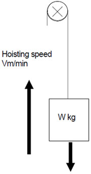
When an object with the mass of W [kg] is hoisted at the speed of V [m/min], the required motor driving force P is as follows:
Example 2
Under the condition that the mass is 50kg, the object speed is 60m/min and the machine efficiency is 0.8, the driving force required for hoisting is:
Sizing the VFD and motor in consideration of acceleration/deceleration
Vector variable frequency drives frequently perform acceleration/deceleration. Select the most suitable capacity size in accordance with the movement of the machine. To make a right selection, check data on the machine side and the operation pattern beforehand. The following shows the steps of the selection.
(1) Find the load torque of the machine.
Load torque: Force that is required to move a load.
(2) Find the inertia moment (J) of the machine.
J: Value that indicates how much difficult to move or stop an object. It can be compared to a load on the back of a truck.
(3) Find the operation pattern of the machine.
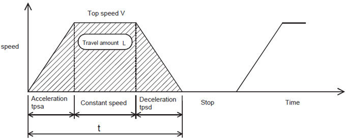
Operation pattern: One cycle of machine operation status derived from travel time and stop time. The gray area below indicates travel amount.

When the top speed is V [mm/s], travel time is t [s], acceleration and deceleration times are respectively tpsa [s] and tpsd [s], travel amount is L [mm], and tpsa=tpsd, their relation is as shown in the following formula.
Tentative selection: Choose a motor that can be the most suitable in reference to the load torque and J. The rated torque of the motor must be larger than the load torque.
(5) Calculate a torque with the motor tentatively selected.
Torque calculation: Calculation that is basically made in accordance with the following four conditions. (Most typical pattern)
Example. V/F control 6Hz ≤ f ≤60Hz
C = (f / 60)0.4
Complement: When, as a feature of variable frequency drives, driving multiple motors with one variable frequency drive, select motors so that a value of (total current of motors) multiplied by (approximately 1.05 to 1.1) does not exceed the rated current of the variable frequency drive.
(6) Check the necessity of a brake resistor for the regenerative brake.
Calculate the braking electric power from the energy generated by the use of the regenerative brake in a deceleration operation. Check if the calculated power is within the permissible range of the performance specifications. Install an external brake resistor (optional) if the power is outside the range
Clearing (1) to (6) completes the steps of a motor and variable frequency drive sizing.
Before buying the right size of a variable frequency drive (VFD), it is necessary to generally know the working environment, the target work and if the performance and functions are satisfied. Based on this information, choose a suitable motor size and a variable frequency drive or a vector VFD to control the AC motor. In terms of the hardware basics, the same concept can be applied to both general purpose VFDs and vector VFDs.
Selecting a motor according to driving force
The formula to obtain the driving force differs depending on horizontal or vertical (up-down) movement.
(1) Horizontal movement
When the total weight of the traveling object is W [Kg], the speed is V [m/min] and the friction factor is μ, the required motor driving force P is calculated as follows:

P = μWV / 6120η [KW]Example 1
Under the condition that the mass is 80kg, the object speed is 80m/min, the friction resistance is 0.2 and the machine efficiency is 0.8, the driving force required for the motor is:

P= 80 × 0.2 × 80 / (6120 × 0.8) = 0.26kW(2) Vertical movement
When an object with the mass of W [kg] is hoisted at the speed of V [m/min], the required motor driving force P is as follows:
P = μWV / 6120η [KW]η: Machine efficiency
Example 2
Under the condition that the mass is 50kg, the object speed is 60m/min and the machine efficiency is 0.8, the driving force required for hoisting is:
P = 50 × 60 / (6120×0.8) = 0.61kW
Sizing the VFD and motor in consideration of acceleration/deceleration
Vector variable frequency drives frequently perform acceleration/deceleration. Select the most suitable capacity size in accordance with the movement of the machine. To make a right selection, check data on the machine side and the operation pattern beforehand. The following shows the steps of the selection.
(1) Find the load torque of the machine.
Load torque: Force that is required to move a load.
(2) Find the inertia moment (J) of the machine.
J: Value that indicates how much difficult to move or stop an object. It can be compared to a load on the back of a truck.
(3) Find the operation pattern of the machine.
Operation pattern: One cycle of machine operation status derived from travel time and stop time. The gray area below indicates travel amount.

When the top speed is V [mm/s], travel time is t [s], acceleration and deceleration times are respectively tpsa [s] and tpsd [s], travel amount is L [mm], and tpsa=tpsd, their relation is as shown in the following formula.
L = V [mm/s] × ( t - tpsa) [mm](4) Tentatively select a motor.
Tentative selection: Choose a motor that can be the most suitable in reference to the load torque and J. The rated torque of the motor must be larger than the load torque.
(5) Calculate a torque with the motor tentatively selected.
Torque calculation: Calculation that is basically made in accordance with the following four conditions. (Most typical pattern)
- Torque required for accelerating to a constant speed from the start.
- Torque required for keeping the load moving at a constant speed.
- Torque required for decelerating to the stop.
- Judge the heat availability of the motor.
Motor equivalent current = √(∑(In2 x tn)) / (∑(Cn x tn))Cn:Cooling factor
Example. V/F control 6Hz ≤ f ≤60Hz
C = (f / 60)0.4
Complement: When, as a feature of variable frequency drives, driving multiple motors with one variable frequency drive, select motors so that a value of (total current of motors) multiplied by (approximately 1.05 to 1.1) does not exceed the rated current of the variable frequency drive.
(6) Check the necessity of a brake resistor for the regenerative brake.
Calculate the braking electric power from the energy generated by the use of the regenerative brake in a deceleration operation. Check if the calculated power is within the permissible range of the performance specifications. Install an external brake resistor (optional) if the power is outside the range
Clearing (1) to (6) completes the steps of a motor and variable frequency drive sizing.
Great content! Thanks.
Post a Comment:
You may also like:
Featured Articles
Variable Frequency Drive Basic Safety ...
 This paper provides guidelines on functional safety considerations when selecting and integrating a variable frequency drive ...
 This paper provides guidelines on functional safety considerations when selecting and integrating a variable frequency drive ...
Variable Frequency Drive Sizing
 Before selecting the size of a variable frequency drive (VFD), it is necessary to generally know the working environment, the ...
 Before selecting the size of a variable frequency drive (VFD), it is necessary to generally know the working environment, the ...
Variable Frequency Drives control AC motor for energy savings by adjustable speed, for short VFD, also named variable speed drives and frequency inverter.

I got an very easy & great information regards VFD.
thanks
Kabeer