Home » Wiki
 Ten or twelve years ago a manufacturing facility might have had only10% of its motors operating with a VFD (variable frequency drive). As technology advanced and VFD's got less expensive you're likely to see up to 75% of motors being run with VFD's in that same plant. With the rising use of VFD's comes the rising awareness of the phenomenon of "shaft current". AEGIS has some great literature on this and sell a grounding ring that we use to discharge the circulating currents that damage bearings. I have a repair shop and when a motor comes in for repair or rewind we make it a practice to ask customers if the motor is run with a VFD. If it is we will cut the bearing races and look for evidence of EDM so we can address it prior to assembly if needed.
A MV VFD is often physically larger than a comparable-power LV configuration. In part, this is because internal clearances have to be greater to prevent arcing faults. Also, the components related to the voltage level are typically larger in the MV VFD, requiring more room to mount.
MV VFDs are - almost exclusively - three phase connections both upstream and downstream from the variable frequency drive. Although a LV VFD can be similarly connected to three phase, there are a large percentage of LV VFDs that are single phase devices (either upstream, downstream, or both).
MV VFDs are - almost exclusively - three phase connections both upstream and downstream from the variable frequency drive. Although a LV VFD can be similarly connected to three phase, there are a large percentage of LV VFDs that are single phase devices (either upstream, downstream, or both).
V/F control
This is a control system in which the ratio of frequency to the output voltage is constant when the frequency is changed. In this system, if the voltage to be actually valid decreases due to a voltage drop in a wiring or the primary coil of a motor, enough amount of torque cannot be output (the slower the speed is, the more this phenomenon affects.). Therefore, the amount of voltage drop estimated in advance is set higher (torque boost) to cover the shortage of the torque at low speed.
Vector control
Detect a motor speed with an encoder and calculate a motor slip to identify the load magnitude. This control is a system which divides the variable frequency drive output current into an excitation current (a current necessary to generate a magnetic flux) and a torque current (a current proportional to the load torque) by vector calculation and controls a frequency and voltage optimally to flow a necessary current individually according to this load magnitude.
1) The leakage breaker or leakage relay may operate unintentionally due to the leakage current between grounds. The leakage current includes many high frequency components that have a relatively small influence on human body.
2) The external thermal relay may operate unintentionally due to the leakage current between cables.

2) The external thermal relay may operate unintentionally due to the leakage current between cables.
A soft starter reduces voltage, not Hertz, and as such the starting torque at 2-3 Hz is next to nothing. The soft starter is essentially robbing the motor of voltage at all points between 0 and 59 Hz, peak (Line) voltage met at 60 Hz. In overhead crane controls, setting a soft start to begin traversal motions with a capacity load on the crane or trolley can result in a 'jack rabbit' starting jump when the crane is unloaded. Or, setting it when unloaded can result in motor thermal trip and no motion achieved when the crane is then capacity loaded.
When compare with a variable frequency drive (VFD), the motor peak design ratio is basically preserved throughout the acceleration ramp. To put this in a general, simple explanation, when a 460 VAC/60 Hz motor is running at 30 Hz, the corresponding voltage to the motor should be in the vicinity of 230 VAC. Changing one value in the Volts to Hertz ratio without changing the other results in significant motor torque loss. A VFD will provide smooth starts from zero to peak speed as with the Hz/Voltage ratio maintained, near peak motor torque is preserved. Unlike a soft starter, it will provide the same balance ratio and control effect in a deceleration ramp as well.
When compare with a variable frequency drive (VFD), the motor peak design ratio is basically preserved throughout the acceleration ramp. To put this in a general, simple explanation, when a 460 VAC/60 Hz motor is running at 30 Hz, the corresponding voltage to the motor should be in the vicinity of 230 VAC. Changing one value in the Volts to Hertz ratio without changing the other results in significant motor torque loss. A VFD will provide smooth starts from zero to peak speed as with the Hz/Voltage ratio maintained, near peak motor torque is preserved. Unlike a soft starter, it will provide the same balance ratio and control effect in a deceleration ramp as well.
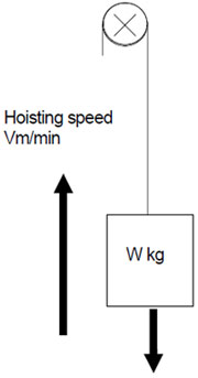
The correct sizing of the variable frequency drive (VFD) system depends on the knowledge of the behavior of the load type, that is, how the load is related with speed and consequently how much torque is demanded on the motor shaft. In most processes the variable frequency drive load type may be described by one of the following terms: variable torque, constant torque and constant horsepower.
Variable torque loads
Typical examples:
Variable torque loads
Typical examples:
- Centrifugal pumps
- Centrifugal fans
- Centrifugal blowers
- Centrifugal compressors
Featured Articles
Variable Frequency Drive Sizing
 Before selecting the size of a variable frequency drive (VFD), it is necessary to generally know the working environment, the ...
Before selecting the size of a variable frequency drive (VFD), it is necessary to generally know the working environment, the ...Single VFD for Multiple Motors
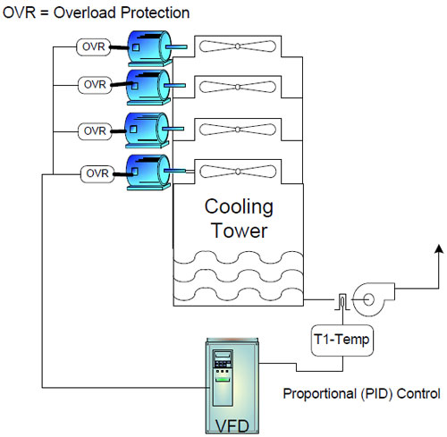 A single variable frequency drive (VFD) may control 2 or 3 motors at a time, multiple motors control is usually done because of ...
A single variable frequency drive (VFD) may control 2 or 3 motors at a time, multiple motors control is usually done because of ...PWM Variable Frequency Drive ...
 Pulse Width Modulation (PWM) voltage source variable frequency drives (VFD) presently comprehend the most used equipments to feed ...
Pulse Width Modulation (PWM) voltage source variable frequency drives (VFD) presently comprehend the most used equipments to feed ...Variable frequency drive for water ...
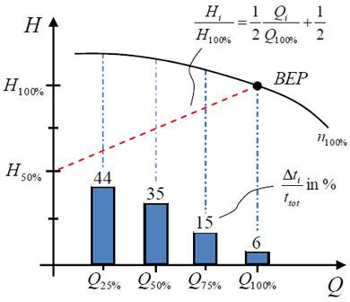 Quantifying the energy efficiency of pump units across markets is a tough task: These units mostly consist of rotodynamic pumps ...
Quantifying the energy efficiency of pump units across markets is a tough task: These units mostly consist of rotodynamic pumps ...Variable Frequency Drive Basic Safety ...
 This paper provides guidelines on functional safety considerations when selecting and integrating a variable frequency drive ...
This paper provides guidelines on functional safety considerations when selecting and integrating a variable frequency drive ...
Variable Frequency Drives control AC motor for energy savings by adjustable speed, for short VFD, also named variable speed drives and frequency inverter.