Home » Applications » Variable frequency drive on refrigeration compressor
Variable frequency drive on refrigeration compressor
Variable Frequency Drive (VFD) technology is an essential component of state-of-the-art refrigeration and climate technology. When compared to conventional refrigeration technology, a few essential changes are required for safe, reliable plant operation. This paper describes in detail how a refrigeration system is dimensioned and how VFDs are installed in a refrigeration system.
Introduction
VFDs have been successfully used now for several years in refrigeration technology.
The advantages of variable frequency drive technology can only be achieved in practice when the overall system is correctly designed. Planning starts with the design of the refrigeration technology, continues through the mechanical and electrical system design and ends with the installation and the commissioning of the various system components.
A variable-speed refrigeration system should basically be considered as a further development of conventional technology where banks of compressors are used.
Using a state-of-the-art VFD controlled refrigeration system, the following benefits should be achieved
Designing of refrigeration power
When designing the refrigeration system, it is necessary to precisely analyze the expected performance profile in this case. The smallest cooling outlet is not decisive, but the lowest refrigeration power which is expected in operation.
A constant suction pressure in the selected temperature range is the basis for the energy saving which is expected. This means that at all of the expected operating points, the minimum refrigeration requirement lies above the lowest refrigeration power of the variable speed compressor.
If a refrigeration system is optimally designed, then the variable speed compressor is in permanent operation. The evaporation temperature can be increased by up to 5 K as a result of permanent operation - 24 hours a day for 365 days a year. This means that between 16 % and 20 % of energy can be saved by using this measure alone. Further, it must be ensured that there is a correct power grading between variable speed compressor and the associated fixed speed compressor used in the compressor pack.
In this case it is important to take into account the increased performance of the refrigeration compressor when using closed-loop frequency control. Depending on what the manufacturer has released, standard compressors, at a frequency of 65 Hz, can provide up to 130 % of their normal refrigeration power. If special motors are used, then theoretically, the refrigeration power can be increased up to 175 % of the normal refrigeration power.
The use of standard condensing units must be verified, taking into consideration the higher refrigeration power and the subsequently higher condenser power. It can be assumed that the electrical power drawn from reciprocating compressors is proportional to the refrigeration power.
The following can apply as a guiding principle when designing a refrigeration system: The refrigeration power to either be switched-in or switched-out must be compensated by reducing or increasing the power of the variable speed compressor.
This means that at the instant that the power is switched, there is almost no change in power achieved, and only the starting point for a closed-loop controlled power adaption is fixed. In order to further reinforce this positive aspect, the fixed speed compressor should be started with a soft starting device. In order to adapt the power, variable speed compressor and fixed speed compressor can be equipped with capacity regulation. Using this equipment, wide power ranges can be implemented even with favorably-priced duo pack systems.
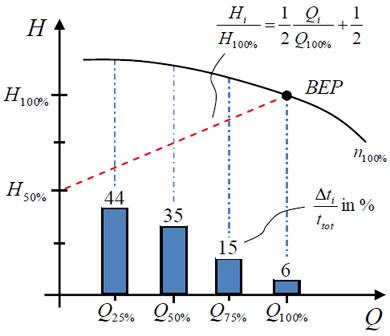
The switching/closed-loop control characteristics of a frequency-controlled refrigeration system are shown schematically in Fig. 1.

Figure 1: Switching/closed-loop control characteristics of a frequency-controlled refrigeration system
The experience gained from many closed-loop frequency controlled refrigeration systems shows that when calculating the refrigeration power required, generally an excessive safety margin is included. In practice, refrigeration systems are generally over dimensioned for operation at the maximum refrigeration load.
This means that the performance range of compressors fed from VFDs cannot be completely utilized. In cases such as these, the compressor operates at between 50 % and 75 % of its maximum power, the power which is switched-in is generally too high and the control behavior fluctuates significantly. However, a fluctuating control characteristic has a negative impact on achieving a stable suction pressure and should therefore be avoided.
Piping system
As planning progresses, increased importance must be placed on designing the piping.
Especially the oil return line should be analyzed in detail with knowledge about the wide power range. In borderline cases, twin suction lines in the rising section of the piping should be used.
Integrating intelligent VFD
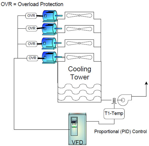
In order to optimize a refrigeration system with an intelligent VFD, it is necessary to clearly understand the features of the electrical and control equipment and the possibilities afforded by using standard equipment. These excerpts describe the electrical design and also provide an example showing how a control system is connected-up in Figure 2.

Figure 2: Block diagram of the power wiring
Planning check list
Summarizing, the following points are important when planning a refrigeration system.
The following special features can be highlighted with reference to the mechanical equipment of the refrigeration compressor. Selecting a suitable compressor is the basis when designing a refrigeration system.
Compressors which are suitable for use with VFDs are those types with the largest motor series within a compressor power stage. From a mechanical perspective, reciprocating compressors as well as scroll compressors are suitable with certain restrictions.
Special emphasis should be placed on a good vibration dampening and decoupling of the compressor assembly within the refrigeration machine. Compressor units fed from VFDs should be rigidly mounted on a base frame. The vibration dampening elements, provided with the compressors, should, for example, be replaced by either plastic or aluminium blocks. Possible vibration can be tolerated and only has to be dampened at the transition to the machine construction. In this case, the compressor assembly should be dampened using elastomers in the machinery design. At the vibration de-coupling transition, rigid pipes should be provided with flexible pipe couplings to dampen vibration.
The recommended mounting techniques described are again shown in Figs. 3.

Figure 3: Vibration damping of a compressor assembly
Oil lubrication of compressors
Special emphasis should be placed on monitoring the oil level in refrigeration compressors. It is especially important to have an adequately dimensioned oil equalization line between the individual compressor casings. It is also advantageous to install an additional connector line for gas equalization. If oil/gas equalization is not correctly dimensioned, then the refrigeration compressor oil shifts within the compressor bank. This results in different oil levels in the crankcase housing. Maximum oil levels can be exceeded and the minimum level can also be reached.
This means that compressors can start with poor lubrication and at the same time, operational compressors could be damaged due to excess oil.
For most applications, serious considerations should be given to using state-of-the-art electronic oil level monitoring with alarm signal.
If oil equalization is not used, then suction line oil receivers adapted to the flow are absolutely necessary. In this case, the oil is fed to the compressors from the oil receiver to the particular compressor via the suction line. However, this type of oil return system should only be considered for solutions where the specific configuration can be planned.
If refrigeration systems are operated in thermal limiting ranges, the compressor application must be coordinated with the particular manufacturers. Compressors in the low-temperature range as well as several two-cylinder models should always be operated with an increased minimum frequency. This guarantees that the motor is cooled, oil is transported and the compressors can be started. The use of a compressed gas-overheating protection can be of advantage, as far as machine safety and plant lifetime are concerned.
Check list for mechanical installation
Summarizing, the following points are important for the mechanical design:
When designing the refrigeration electrical system, the following specific points can be considered. VFDs generate high-frequency harmonics.
When the motor cables are incorrectly screened, these high frequencies can cause disturbances in adjacent cables and modules. High frequency currents flow along the surface of the conductor. This means that it is especially important that the screening is connected through the largest possible surface area. Screens which are twisted together act like antennas and radiate noise to other modules. Fig. 4 indicates how the cable screens should be connected to provide the most effective cable shielding effects.

Figure 4: Cable screening
It is important to use cables with copper screens. These are designated by the code YSLY-CY-xxx. The screens of high frequency cables should be connected at both ends. This means that at each of the cable ends! The same cable types should be used for analog sensor cables, however, the screen should be connected to ground at one end at the VFD. A drive system is symbolically shown with the appropriate electrical connections of the screened cable sections in the load circuit of the VFD in Fig. 5.

Figure 5: Installation example for a load circuit
The power section of VFDs, filters and switching devices should be directly connected to the mounting plate using ground strips. All of the switching devices must be equipped with RC elements to protect the control systems!
We recommend that analog filter modules are installed in the electrical enclosure. This means that the control signals are again smoothed here and the control quantity of the overall system increased. Fig. 6 shows how the filter modules are integrated into the sensor wiring.

Figure 6: Schematic of a signal filter
For critical plant configurations we recommend that motor filters are used between the VFD output and motor.
This means that a sinusoidal voltage characteristic is generated from the pulse-width modulated square wave voltages which is then fed to the motor. This is important for motors with low winding insulation and standard fans on heat exchangers.
The devices must be arranged so that the voltage rate-of-rise, specified by the compressor manufacturer is maintained. DIN VDE 530 - the applicable standard - specifies a value of dv/dt DIN VDE 530 - the applicable standard - specifies a value of dv/dt <1300 V/ms. This value applies for standard motors and deviates from the limit values of compressor motors fed from VFDs which have been approved for VFD operation.
Universal residual-current protective devices must be used. These types of devices can be purchased through electrical distributors. If other devices are used, then it must be expected that the protective device can erroneously trip in normal operation due to the induced current flowing through the shielding. In extreme situations, it is possible that devices don't even trip which means that effective protection is then not guaranteed.
The cable cross-sections should be selected corresponding to the tables of the VFD manufacturer.
Other cross-sections are only permissible by using an additional protective device dimensioned according to the cable cross-section. In this case, the maximum current levels occurring in the individual plant sections should be used as basis for selecting the protective devices.
When the appropriate guidelines are observed, cable lengths of up to 30 m can be used without any problem. If a VFD simultaneously supplies several drives, then the individual length must be added. A motor reactor is required if the total length of the motor cables exceeds that specified by the VFD manufacturer. This motor reactor must be harmonized with the particular VFD.
Cables conducting high-frequency signals must always be separately routed away from control and sensor cables. This is true within switchgear installations and especially in the refrigeration system itself. If a separate cable duct cannot be implemented in the system, then we recommend that radiating "high frequency" cables are routed in grounded steel pipes.
Electrical enclosure
The VFD must be mounted in the switchgear panel, carefully observing the manufacturer's specifications. Fig. 7 show typical specified clearances to other modules.

Figure 7: Clearances when mounting VFD
It is important to maintain the terminal limit values of the modules accommodated in the electrical enclosure. When VFDs and soft starters are accommodated in electrical enclosure, it is essential to provide adequate cooling. The enclosure cooling or ventilation should be dimensioned corresponding to the power losses specified by the device manufacturers.
As an approximation, an airflow of 50 m³/h is required for every 100 Watt of dissipated heat. If the maximum temperature of 40 °C is exceeded, then the modules are subject to increased wear and automatically shut themselves down when the maximum permissible operating temperature is reached. This can result in plant sections being shut down or the complete failure of the overall installation.
If standard motors are to be operated at 65 Hz, then it is necessary to increase the voltage by using a transformer at the input of the VFD. This transformer increases the voltage, for example, from 400 V to an output voltage of 440 V. This means that the voltage to frequency ratio of the motor is kept constant.
Summarizing, the following points are important for the electrical installation:
Glance to the future
In a time of increasing energy costs and environmental legislation, it has become certainly more important to save energy. When compared to stepping switches, continuous power control of compressors using variable-speed with VFDs is an optimum solution.
The compressor power is precisely adapted to the required refrigeration power without having to leave the optimum and required operating point. Not only this, the compressor efficiency is significantly improved.
The following advantages are obtained as a result of the pressure relationships in the suction gas area, even when the refrigeration system load fluctuates:
Introduction
VFDs have been successfully used now for several years in refrigeration technology.
The advantages of variable frequency drive technology can only be achieved in practice when the overall system is correctly designed. Planning starts with the design of the refrigeration technology, continues through the mechanical and electrical system design and ends with the installation and the commissioning of the various system components.
A variable-speed refrigeration system should basically be considered as a further development of conventional technology where banks of compressors are used.
Using a state-of-the-art VFD controlled refrigeration system, the following benefits should be achieved
- The operating costs reduced
- The products and goods being refrigerated positively influenced
- The system power ratings adapted to the actual cooling requirements and reliable and stable refrigeration
Designing of refrigeration power
When designing the refrigeration system, it is necessary to precisely analyze the expected performance profile in this case. The smallest cooling outlet is not decisive, but the lowest refrigeration power which is expected in operation.
A constant suction pressure in the selected temperature range is the basis for the energy saving which is expected. This means that at all of the expected operating points, the minimum refrigeration requirement lies above the lowest refrigeration power of the variable speed compressor.
If a refrigeration system is optimally designed, then the variable speed compressor is in permanent operation. The evaporation temperature can be increased by up to 5 K as a result of permanent operation - 24 hours a day for 365 days a year. This means that between 16 % and 20 % of energy can be saved by using this measure alone. Further, it must be ensured that there is a correct power grading between variable speed compressor and the associated fixed speed compressor used in the compressor pack.
In this case it is important to take into account the increased performance of the refrigeration compressor when using closed-loop frequency control. Depending on what the manufacturer has released, standard compressors, at a frequency of 65 Hz, can provide up to 130 % of their normal refrigeration power. If special motors are used, then theoretically, the refrigeration power can be increased up to 175 % of the normal refrigeration power.
The use of standard condensing units must be verified, taking into consideration the higher refrigeration power and the subsequently higher condenser power. It can be assumed that the electrical power drawn from reciprocating compressors is proportional to the refrigeration power.
The following can apply as a guiding principle when designing a refrigeration system: The refrigeration power to either be switched-in or switched-out must be compensated by reducing or increasing the power of the variable speed compressor.
This means that at the instant that the power is switched, there is almost no change in power achieved, and only the starting point for a closed-loop controlled power adaption is fixed. In order to further reinforce this positive aspect, the fixed speed compressor should be started with a soft starting device. In order to adapt the power, variable speed compressor and fixed speed compressor can be equipped with capacity regulation. Using this equipment, wide power ranges can be implemented even with favorably-priced duo pack systems.
The switching/closed-loop control characteristics of a frequency-controlled refrigeration system are shown schematically in Fig. 1.
Figure 1: Switching/closed-loop control characteristics of a frequency-controlled refrigeration system
The experience gained from many closed-loop frequency controlled refrigeration systems shows that when calculating the refrigeration power required, generally an excessive safety margin is included. In practice, refrigeration systems are generally over dimensioned for operation at the maximum refrigeration load.
This means that the performance range of compressors fed from VFDs cannot be completely utilized. In cases such as these, the compressor operates at between 50 % and 75 % of its maximum power, the power which is switched-in is generally too high and the control behavior fluctuates significantly. However, a fluctuating control characteristic has a negative impact on achieving a stable suction pressure and should therefore be avoided.
Piping system
As planning progresses, increased importance must be placed on designing the piping.
Especially the oil return line should be analyzed in detail with knowledge about the wide power range. In borderline cases, twin suction lines in the rising section of the piping should be used.
Integrating intelligent VFD
In order to optimize a refrigeration system with an intelligent VFD, it is necessary to clearly understand the features of the electrical and control equipment and the possibilities afforded by using standard equipment. These excerpts describe the electrical design and also provide an example showing how a control system is connected-up in Figure 2.
Figure 2: Block diagram of the power wiring
Planning check list
Summarizing, the following points are important when planning a refrigeration system.
- Dimension of the refrigeration compressor according to the minimum power requirement expected
- Adapt the power stages to the refrigeration system installation
- Calculate the refrigeration power without including excessive safety margins
- Select a condenser for the maximum compressor frequency
- Analyze the electrical requirements
- Use standard equipment
The following special features can be highlighted with reference to the mechanical equipment of the refrigeration compressor. Selecting a suitable compressor is the basis when designing a refrigeration system.
Compressors which are suitable for use with VFDs are those types with the largest motor series within a compressor power stage. From a mechanical perspective, reciprocating compressors as well as scroll compressors are suitable with certain restrictions.
Special emphasis should be placed on a good vibration dampening and decoupling of the compressor assembly within the refrigeration machine. Compressor units fed from VFDs should be rigidly mounted on a base frame. The vibration dampening elements, provided with the compressors, should, for example, be replaced by either plastic or aluminium blocks. Possible vibration can be tolerated and only has to be dampened at the transition to the machine construction. In this case, the compressor assembly should be dampened using elastomers in the machinery design. At the vibration de-coupling transition, rigid pipes should be provided with flexible pipe couplings to dampen vibration.
The recommended mounting techniques described are again shown in Figs. 3.
Figure 3: Vibration damping of a compressor assembly
Oil lubrication of compressors
Special emphasis should be placed on monitoring the oil level in refrigeration compressors. It is especially important to have an adequately dimensioned oil equalization line between the individual compressor casings. It is also advantageous to install an additional connector line for gas equalization. If oil/gas equalization is not correctly dimensioned, then the refrigeration compressor oil shifts within the compressor bank. This results in different oil levels in the crankcase housing. Maximum oil levels can be exceeded and the minimum level can also be reached.
This means that compressors can start with poor lubrication and at the same time, operational compressors could be damaged due to excess oil.
For most applications, serious considerations should be given to using state-of-the-art electronic oil level monitoring with alarm signal.
If oil equalization is not used, then suction line oil receivers adapted to the flow are absolutely necessary. In this case, the oil is fed to the compressors from the oil receiver to the particular compressor via the suction line. However, this type of oil return system should only be considered for solutions where the specific configuration can be planned.
If refrigeration systems are operated in thermal limiting ranges, the compressor application must be coordinated with the particular manufacturers. Compressors in the low-temperature range as well as several two-cylinder models should always be operated with an increased minimum frequency. This guarantees that the motor is cooled, oil is transported and the compressors can be started. The use of a compressed gas-overheating protection can be of advantage, as far as machine safety and plant lifetime are concerned.
Check list for mechanical installation
Summarizing, the following points are important for the mechanical design:
- Select compressors which are mechanically suitable
- Select the motor with the largest power rating of the compressor series
- Rigidly mount the compressor including the associated components
- Generously dimension the oil-gas equalization
- Consider using oil level control
- Consider using compressed gas temperature monitoring
- Investigate the application limits of the compressor when using VFDs
When designing the refrigeration electrical system, the following specific points can be considered. VFDs generate high-frequency harmonics.
When the motor cables are incorrectly screened, these high frequencies can cause disturbances in adjacent cables and modules. High frequency currents flow along the surface of the conductor. This means that it is especially important that the screening is connected through the largest possible surface area. Screens which are twisted together act like antennas and radiate noise to other modules. Fig. 4 indicates how the cable screens should be connected to provide the most effective cable shielding effects.
Figure 4: Cable screening
It is important to use cables with copper screens. These are designated by the code YSLY-CY-xxx. The screens of high frequency cables should be connected at both ends. This means that at each of the cable ends! The same cable types should be used for analog sensor cables, however, the screen should be connected to ground at one end at the VFD. A drive system is symbolically shown with the appropriate electrical connections of the screened cable sections in the load circuit of the VFD in Fig. 5.
Figure 5: Installation example for a load circuit
The power section of VFDs, filters and switching devices should be directly connected to the mounting plate using ground strips. All of the switching devices must be equipped with RC elements to protect the control systems!
We recommend that analog filter modules are installed in the electrical enclosure. This means that the control signals are again smoothed here and the control quantity of the overall system increased. Fig. 6 shows how the filter modules are integrated into the sensor wiring.
Figure 6: Schematic of a signal filter
For critical plant configurations we recommend that motor filters are used between the VFD output and motor.
This means that a sinusoidal voltage characteristic is generated from the pulse-width modulated square wave voltages which is then fed to the motor. This is important for motors with low winding insulation and standard fans on heat exchangers.
The devices must be arranged so that the voltage rate-of-rise, specified by the compressor manufacturer is maintained. DIN VDE 530 - the applicable standard - specifies a value of dv/dt DIN VDE 530 - the applicable standard - specifies a value of dv/dt <1300 V/ms. This value applies for standard motors and deviates from the limit values of compressor motors fed from VFDs which have been approved for VFD operation.
Universal residual-current protective devices must be used. These types of devices can be purchased through electrical distributors. If other devices are used, then it must be expected that the protective device can erroneously trip in normal operation due to the induced current flowing through the shielding. In extreme situations, it is possible that devices don't even trip which means that effective protection is then not guaranteed.
The cable cross-sections should be selected corresponding to the tables of the VFD manufacturer.
Other cross-sections are only permissible by using an additional protective device dimensioned according to the cable cross-section. In this case, the maximum current levels occurring in the individual plant sections should be used as basis for selecting the protective devices.
When the appropriate guidelines are observed, cable lengths of up to 30 m can be used without any problem. If a VFD simultaneously supplies several drives, then the individual length must be added. A motor reactor is required if the total length of the motor cables exceeds that specified by the VFD manufacturer. This motor reactor must be harmonized with the particular VFD.
Cables conducting high-frequency signals must always be separately routed away from control and sensor cables. This is true within switchgear installations and especially in the refrigeration system itself. If a separate cable duct cannot be implemented in the system, then we recommend that radiating "high frequency" cables are routed in grounded steel pipes.
Electrical enclosure
The VFD must be mounted in the switchgear panel, carefully observing the manufacturer's specifications. Fig. 7 show typical specified clearances to other modules.
Figure 7: Clearances when mounting VFD
It is important to maintain the terminal limit values of the modules accommodated in the electrical enclosure. When VFDs and soft starters are accommodated in electrical enclosure, it is essential to provide adequate cooling. The enclosure cooling or ventilation should be dimensioned corresponding to the power losses specified by the device manufacturers.
As an approximation, an airflow of 50 m³/h is required for every 100 Watt of dissipated heat. If the maximum temperature of 40 °C is exceeded, then the modules are subject to increased wear and automatically shut themselves down when the maximum permissible operating temperature is reached. This can result in plant sections being shut down or the complete failure of the overall installation.
If standard motors are to be operated at 65 Hz, then it is necessary to increase the voltage by using a transformer at the input of the VFD. This transformer increases the voltage, for example, from 400 V to an output voltage of 440 V. This means that the voltage to frequency ratio of the motor is kept constant.
Summarizing, the following points are important for the electrical installation:
- Cable screens must be connected to ground through the largest possible surface area
- For motor cables the cable screens must be connected to ground at both ends
- The screens of sensor cables must be connected at one end to ground at the VFD
- Additionally connect the control electronics to ground potential
- Equip connectors with RC damping elements
- Carefully observe cable length
- Include sensor filters
- Apply measures to reliably dissipate power loss
Glance to the future
In a time of increasing energy costs and environmental legislation, it has become certainly more important to save energy. When compared to stepping switches, continuous power control of compressors using variable-speed with VFDs is an optimum solution.
The compressor power is precisely adapted to the required refrigeration power without having to leave the optimum and required operating point. Not only this, the compressor efficiency is significantly improved.
The following advantages are obtained as a result of the pressure relationships in the suction gas area, even when the refrigeration system load fluctuates:
- Temperature fluctuations at the refrigeration points are reduced
- Higher relative air humidity
- Improved quality of the refrigerated goods
- Reduced condenser icing
- Extended de-icing intervals
Post a Comment:
You may also like:
Featured Articles
Variable frequency drive for water ...
 Quantifying the energy efficiency of pump units across markets is a tough task: These units mostly consist of rotodynamic pumps ...
Quantifying the energy efficiency of pump units across markets is a tough task: These units mostly consist of rotodynamic pumps ...Single VFD for Multiple Motors
 A single variable frequency drive (VFD) may control 2 or 3 motors at a time, multiple motors control is usually done because of ...
A single variable frequency drive (VFD) may control 2 or 3 motors at a time, multiple motors control is usually done because of ...Select a right Variable Frequency Drive
 Before selecting a Variable Frequency Drive (VFD) for an existing electric motor, it's important to know the purpose and ...
Before selecting a Variable Frequency Drive (VFD) for an existing electric motor, it's important to know the purpose and ...VFD on air compressor considerations
 When installing a variable frequency drive is that the air ends (i.e. impellers) are usually custom made for the air compressor. ...
When installing a variable frequency drive is that the air ends (i.e. impellers) are usually custom made for the air compressor. ...
Variable Frequency Drives control AC motor for energy savings by adjustable speed, for short VFD, also named variable speed drives and frequency inverter.