Variable Frequency Drive Cables Recommendations
The maximum peak voltage appearing at the terminals of the variable frequency drive (VFD) fed motor depends on many factors, predominantly the cable length.
When supplying motors with variable frequency drives, the following practical rules are suggested for the evaluation of the need of using filters between motor and variable frequency drive.
The output reactor is necessary for the eddy current that flows from variable frequency drive to earth to be limited. The input (line) reactor prevents the variable frequency drive ground fault from tripping.
The output reactor design must take account of additional losses occurring due to current ripple and current leakage to earth, which increases as cable length rises. For long cables and reactors designed for small currents there will be great influence of the leakage currents on the reactor losses (and heating). The cooling system of the variable frequency drive panel must also take the reactors additional losses into account for a safe temperature operation to be assured.
The output reactor must be installed near the variable frequency drive, as shown below.

L1 = Line reactor
L2 = Output reactor – must be installed next to the variable frequency drive.
Cable types and installation recommendations
The characteristics of the cable connecting motor and VFD, as well as its interconnection and physical location, are extremely important to avoid electromagnetic interference in other devices.
Installation recommendations
IEC 60034-25 presents cable types and construction details. The basic given recommendations are summarized in the figures below. For more details and updated information the current standard version shall be consulted.
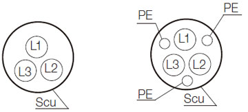
Examples of shielded cables recommended by IEC 60034-25

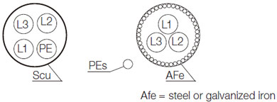
Alternate motor cables for conductors up to 10 mm2

The grounding system must be capable to provide good connections among equipments, for example, between motor and variable frequency drive frame. Voltage or impedance differences between earthing points can cause the flow of leakage currents (common mode currents) and electromagnetic interference.
Symmetrical Shielded Cables: three-core cable (with or without conductors for protective earth) symmetrically constructed + a concentric copper or aluminum protective shield/armour
PE = protective earth conductor
SCU = concentric copper (or aluminum) screen
Cable shield must be grounded at both ends, motor and variable frequency drive. Good EMC practices such as 360° bonding of the shields are recommended, in order for low impedance for high frequency to be provided.
For the shield to operate also as protective conductor, it should have at least 50% of the phase conductors' conductance. If the shield does not have enough crosssection for that, then a separate earth conductor is needed and the shield provides EMC and physical protection only. The shield high-frequency conductance should be at least 10% of that of the phase conductors.
When supplying motors with variable frequency drives, the following practical rules are suggested for the evaluation of the need of using filters between motor and variable frequency drive.
|
Cable length L |
Output filters |
|
L ≤ 100 m |
Not needed |
|
100 m < L ≤ 300 m |
Output reactor needed (at least 2% voltage drop) |
|
L > 300 m |
Special filters needed (contact Gozuk) |
The output reactor is necessary for the eddy current that flows from variable frequency drive to earth to be limited. The input (line) reactor prevents the variable frequency drive ground fault from tripping.
The output reactor design must take account of additional losses occurring due to current ripple and current leakage to earth, which increases as cable length rises. For long cables and reactors designed for small currents there will be great influence of the leakage currents on the reactor losses (and heating). The cooling system of the variable frequency drive panel must also take the reactors additional losses into account for a safe temperature operation to be assured.
The output reactor must be installed near the variable frequency drive, as shown below.

L1 = Line reactor
L2 = Output reactor – must be installed next to the variable frequency drive.
Cable types and installation recommendations
The characteristics of the cable connecting motor and VFD, as well as its interconnection and physical location, are extremely important to avoid electromagnetic interference in other devices.
Unshielded cables
- Three-core unshielded motor cables can be used when there is no need to fulfill the requirements of the European EMC Directives (89/336/EEC).
- Certain minimum distances between motor cables and other electrical cables must be observed in the final installation. These are defined in the table below.
- Emission from cables can be reduced if they are installed together on a metallic cable bridge which is bonded to the earthing system at least at both ends of the cable run. The magnetic fields from these cables may induce currents in nearby metalwork leading to heating and increasing losses.
Shielded cables
- They help to reduce the radiated emission through the motor cables in the Radio Frequency range (RF).
- They are necessary when the installation must comply with the EMC Directive 89/336/EEC as per EN 61800-3.
- They are also necessary when using Radio Frequency Interference Filter (whether built-in or external) at variable frequency drive input.
- Minimum distances between motor cables and other electrical cables (for instance, signal cables, sensor cables, etc.) must be observed in the final installation, as per table below.
|
Recommended separation distances between motor cable (shielded or not) and other cables of the installation |
|
|
Cable Length |
Minimum separation distance |
|
≤ 30 m |
≥ 10 cm |
|
> 30 m |
≥ 25 cm |
Installation recommendations
IEC 60034-25 presents cable types and construction details. The basic given recommendations are summarized in the figures below. For more details and updated information the current standard version shall be consulted.
Examples of shielded cables recommended by IEC 60034-25

Alternate motor cables for conductors up to 10 mm2

The grounding system must be capable to provide good connections among equipments, for example, between motor and variable frequency drive frame. Voltage or impedance differences between earthing points can cause the flow of leakage currents (common mode currents) and electromagnetic interference.
Symmetrical Shielded Cables: three-core cable (with or without conductors for protective earth) symmetrically constructed + a concentric copper or aluminum protective shield/armour
PE = protective earth conductor
SCU = concentric copper (or aluminum) screen
Cable shield must be grounded at both ends, motor and variable frequency drive. Good EMC practices such as 360° bonding of the shields are recommended, in order for low impedance for high frequency to be provided.
For the shield to operate also as protective conductor, it should have at least 50% of the phase conductors' conductance. If the shield does not have enough crosssection for that, then a separate earth conductor is needed and the shield provides EMC and physical protection only. The shield high-frequency conductance should be at least 10% of that of the phase conductors.
Post a Comment:
You may also like:
Featured Articles
PWM Variable Frequency Drive ...
 Pulse Width Modulation (PWM) voltage source variable frequency drives (VFD) presently comprehend the most used equipments to feed ...
 Pulse Width Modulation (PWM) voltage source variable frequency drives (VFD) presently comprehend the most used equipments to feed ...
Variable Frequency Drive Working ...
 This guideline discusses variable frequency drive (VFD) basic working principle and how installing variable frequency drives in ...
 This guideline discusses variable frequency drive (VFD) basic working principle and how installing variable frequency drives in ...
Variable Frequency Drives control AC motor for energy savings by adjustable speed, for short VFD, also named variable speed drives and frequency inverter.
