PWM Variable Frequency Drive Characteristics
Pulse Width Modulation (PWM) voltage source variable frequency drives (VFD) presently comprehend the most used equipments to feed low voltage industrial motors in applications that involve speed variation. PWM VFD works as an interface between the energy source (AC power line) and the induction motor.
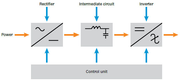
In order to obtain an output signal of desired voltage and frequency, the input signal must accomplish three stages within a PWM VFD:

NOTES:
There are basically two variable frequency drive control types: scalar (open loop) and vector (open or closed loop).
The scalar control is based on the original concept of a VFD: a signal of certain voltage/frequency ratio is imposed onto the motor terminals and this ratio is kept constant throughout a frequency range, in order to keep the magnetizing flux of the motor practically unchanged. It is generally applied when there is no need of fast responses to torque and speed commands and is particularly interesting when there are multiple motors connected to a single VFD. The control is open loop and the speed precision obtained is a function of the motor slip, which depends on the load, since the frequency is imposed on the stator windings. In order to improve the performance of the motor at low speeds, some VFDs make use of special functions such as slip compensation (attenuation of the speed variation as function of load) and torque boost (increase of the V/f ratio to compensate for the voltage drop due to the stator resistance), so that the torque capacity of the motor is maintained. This is the most used VFD's control type owing to its simplicity and also to the fact that the majority of applications do not require high precision or fast responses of the speed control.
The vector control enables VFD fast responses and high level of precision on the motor speed and torque control. Essentially the motor current is decoupled into two vectors, one to produce the magnetizing flux and the other to produce torque, each of them regulated separately. It can be open loop (sensorless) or closed loop (feedback).
In order to obtain an output signal of desired voltage and frequency, the input signal must accomplish three stages within a PWM VFD:
Diode bridge - Rectification of the AC input voltage - constant amplitude and frequency - coming from the power grid;The following diagram depicts the three stages of a Pulse Width Modulation VFD.
DC link or filter - Regulation/smoothing of the rectified signal with energy storage through a capacitor bank;
IGBT power transistors – Inversion of the voltage coming from the link DC into an alternate signal of variable voltage and frequency.
NOTES:
Under light load (or at no load) conditions, the DC link voltage tends to stabilize at √2 Vrede ≈ 1.41 Vrede, However, when the motor drives heavier loads (for instance, at full load), the DC link voltage tends to the value (3/π) √2 Vrede ≈ 1.35 Vrede.
The criteria used to define the insulation system of Gozuk motors fed by PWM variable frequency drives, presented further on, consider the highest of those values (1.41Vin), which is more critical to the motor. In this way the motors attend both situations satisfactorily.
PWM VFD Control Types
There are basically two variable frequency drive control types: scalar (open loop) and vector (open or closed loop).
The scalar control is based on the original concept of a VFD: a signal of certain voltage/frequency ratio is imposed onto the motor terminals and this ratio is kept constant throughout a frequency range, in order to keep the magnetizing flux of the motor practically unchanged. It is generally applied when there is no need of fast responses to torque and speed commands and is particularly interesting when there are multiple motors connected to a single VFD. The control is open loop and the speed precision obtained is a function of the motor slip, which depends on the load, since the frequency is imposed on the stator windings. In order to improve the performance of the motor at low speeds, some VFDs make use of special functions such as slip compensation (attenuation of the speed variation as function of load) and torque boost (increase of the V/f ratio to compensate for the voltage drop due to the stator resistance), so that the torque capacity of the motor is maintained. This is the most used VFD's control type owing to its simplicity and also to the fact that the majority of applications do not require high precision or fast responses of the speed control.
The vector control enables VFD fast responses and high level of precision on the motor speed and torque control. Essentially the motor current is decoupled into two vectors, one to produce the magnetizing flux and the other to produce torque, each of them regulated separately. It can be open loop (sensorless) or closed loop (feedback).
- Speed feedback – a speed sensor (for instance, an incremental encoder) is required on the motor. This control mode provides great accuracy on both torque and speed of the motor even at very low (and zero) speeds.
- Sensorless – simpler than the closed loop control, but its action is limited particularly at very low speeds. At higher speeds this control mode is practically as good as the feedback vector control.
Post a Comment:
You may also like:
Featured Articles
Variable Frequency Drive Working ...
 This guideline discusses variable frequency drive (VFD) basic working principle and how installing variable frequency drives in ...
This guideline discusses variable frequency drive (VFD) basic working principle and how installing variable frequency drives in ...PWM Variable Frequency Drive ...
 Pulse Width Modulation (PWM) voltage source variable frequency drives (VFD) presently comprehend the most used equipments to feed ...
Pulse Width Modulation (PWM) voltage source variable frequency drives (VFD) presently comprehend the most used equipments to feed ...
Variable Frequency Drives control AC motor for energy savings by adjustable speed, for short VFD, also named variable speed drives and frequency inverter.