Variable frequency drive glossary
This paper explains the basic glossary of variable frequency drive (VFD).
Absolute (absolute position) encoder <Antonym; Incremental encoder>
This is an encoder which can output the angle data within one rotation of the encoder to the outside, and the one which can take out 360 ℃ in 8 to 12-bit data is generally used. If using the encoder as a servo motor encoder, the position within one revolution of the motor is identified. Therefore, this is used when the absolute positioning system is configured with a rotation amount counter.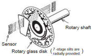
The following figure shows the common structure of the absolute position encoder. In this case, the absolute position signal of 7 bits is output.
Absolute (absolute position) positioning
This is a positioning method in which the absolute coordinate based on the home position is set in the range of machine movement and specified in the positioning data.
Acceleration
This is a change of the motor speed by variable frequency drive, which is expressed with ratio to the acceleration time, and is a slope to the time of motor speed change.
Acceleration time
This is a time which is taken to reach from the current motor speed to the next motor speed when the motor speed is changed by variable frequency drive.
Acceleration time constant
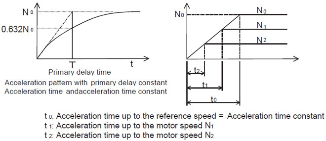
This is a time which is taken from start to end of the acceleration when the motor is accelerated from the stop status to the certain motor speed (rated motor speed, parameter limit speed, etc.).
For the acceleration pattern of the primary delay function, it indicates the time taken when the actual speed reaches to 63.5% of the target speed.
All digital control (Digital control)
This is a system which is controlled by a micro computer or a circuit configured with the peripheral LSI and logic IC.
Analog control
This is a control system which is realized with a control circuit comprised of analog devices such as an operational amplifier.
Angular frequency (ω)
The number of cycles per second is expressed in Hz (hertz) as a unit to express the continuous sine wave, and it is called angular frequency when expressed in angle (radian). It is converted to 2лf [rad/sec] at frequency f [Hz].
Auto tuning (Offline auto tuning/Online auto tuning)
The offline auto tuning is a function with which a variable frequency drive itself measures and stores a necessary motor constant.
The online auto tuning is a function with which the status of the motor is quickly tuned at a start. Therefore, the high accuracy operation unaffected by the motor temperature and stable operation with high torque down to ultra low speed can be performed.
Auto tuning (Real time auto tuning)
The performance (especially response and stability) of a machine driven by the servo motor depends on the characteristics (inertial moment and rigidity) of the machine. Consequently, an adjustment operation is necessary to raise the machine performance to the best condition, and this operation is called tuning.
The auto tuning is a function with which automatically operates the tuning mentioned above and normally indicates a function with which automatically adjusts the speed and position loop gains to be set by a servo amplifier.
The real time auto tuning indicates a function with which a tuning is automatically performed by always tracking, especially when the machine characteristics are changed during operation.
Capacitor regeneration
This is a method to perform a regenerative operation by charging the regenerative energy in the capacitor of the main circuit. Since the heat is not generated, the capacitor can be repeatedly used when the regenerative energy is smaller than the energy charged in the capacitor. However, the method is only applied to small capacity models since the energy, which can be charged in the capacitor, is small.
Differential transmission system
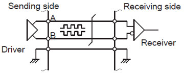
This is a system in which one signal is simultaneously transmitted in pair with a signal of reversed polarity. Since the logic of the signals can be evaluated at the same time on the receiving side, this system has superior noise resistance and is used for a signal transmission at high speed such as the input and output of pulse trains. Generally, the sending side is called driver and the receiving side receiver, and a dedicated IC is used.
Digital control <Antonym; Analog control>
This is a control system which is realized with a control circuit comprised of digital devices. In these days, a system, in which an operation is processed with software using a micro computer or micro processor for the increase of the calculation amount, has become common.
The merits of the digital control system are that there is no temperature drift and the performance is stable and has a high-repeatability.
Droop pulses and stop settling time
Droop pulses represent the gap between the command pulses counted with the deviation counter of a servo amplifier and the feedback pulses of a position encoder. A constant amount of the droop pulse exists in the deviation counter during the operation at a constant speed. As the speed varies, the number of the droop pulses also varies.
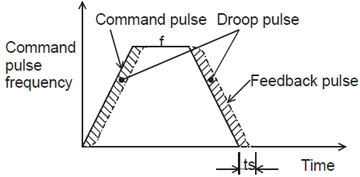
Since the servo motor rotates with a delay behind a command for the amount of the droop purses of the servo amplifier, it stops a little bit behind the command completion. This delay time is called stop settling time.
Dynamic brake
This is a break function to be used for stopping a machine rapidly at a power failure or a servo amplifier failure, and a large break torque is obtained from an electromagnetic brake. However, there is no holding torque during stop. This function is not provided for the IM servo with an induction motor.
Electronic gear
This indicates that the feedback pulse ratio to a command pulse is changed. However, the position resolution is not changed since it is determined with an encoder. The ratio change can be made using fractions with parameters.
Unlike a mechanical gear, the motor torque is not increased even if the ratio magnification is increased.
Error excessive
This means that droop pulses exceed the capacity of the deviation counter. When an overflow occurs on the deviation counter in the positioning system, an accurate positioning cannot be made. In this condition, a servo amplifier or positioning module stops the machine with outputting the error excessive error.
Feed forward control
This is a control which outputs a speed command before droop pulses increase when a pulse command is input in the position loop control.
Feedback control
This is a control which detects a gap between a command and an actual speed with a closed loop and compensates the command value to reduce this gap.
Frequency response (characteristic)
This expresses the speed response quantitatively. The frequency to which the actual motor can respond is indicated in ωc [rad/sec] or fc [Hz] when the speed command is changed into a sine wave pattern as a extremely low-speed command of approximately 10r/min. This frequency response can be enhanced by increasing the speed loop gain. However, if it is increased too much, a vibration or stability easily occurs due to the rigidity of a mechanical system.
Gain search
A personal computer searches the value of the shortest settling time with little overshoot or vibration while automatically changing the gain. This function exhibits the best performance when a high-level adjustment is required.
Grounding
This indicates a condition in which either a cable (P or N after a diode rectification) of the main power supply circuit of the servo amplifier or a power line (U, V or W) of the motor is short-circuited with the earth.
IGBT (Insulated Gate Bipolar Transistor)
Compared to the existing transistor, IGBT is available for high-speed switching and is better for the current, pressure resistance, etc.
Impact drop
This expresses the temporal response characteristic as a value indicating the fluctuation range of the output to the input command in the feed back control. The value is indicated with the size and duration time of the temporary movement amount for when the load is changed in a staircase pattern. Especially, it will be effective when including an integral operation.
Incremental (relative position) positioning
This is a relative positioning in the machine movement. In the positioning data, the positioning is executed by specifying the travel from the current position as a reference (home position). This positioning system is used for the fixed-feed of the roll feed, etc.
Inertia (Inertia moment)
Refer to "Inertia moment".
Inertia moment (Inertia)
This is the amount which indicates the rotation gravity of a rotator and is equivalent to the mass of the linear operation.
M: Mass [kg]
r: Rotation radius [cm]
In addition, GD2 is usually used as the amount to indicate the inertia moment. The r (radius) of the equation above is expressed in 2r (diameter), and there is a relationship as shown below.
Instantaneous power failure
The servo amplifier and variable frequency drive keep the control when the power failure is very short (normally, 15msec or less). However, if the power failure is longer than 15msec, they stop the control with outputting an instantaneous power failure error. If the power failure continues (normally, several 100msec or more), as in the case of power off, they are recovered to the same condition as at power on by power restoration.
The power failure, which is 15msec or more and several 100msec or less as described above, is normally called instantaneous power failure, and the instantaneous power failure error is hold.
Machine analyzer
By connecting to a servo motor, this automatically vibrates the servo motor and analyzes the frequency characteristic of the mechanical system. Although this analysis varies depending on the performance of personal computer, it can be completed in approximately 30 seconds.
Model adaptive control
This is a control system which is used for the servo amplifiers of variable frequency drives. It has an ideal servo amplifier and load (high rigidity and no backlash, etc.) as an ideal model on the software and exhibits the best performance at the actual load with always adapting the actual operation.
Motor electromagnetic brake
The electromagnetic brake, which is installed on the motor with the electromagnetic brake, is a no-excitation operation brake to be used in a up-and-down drive, etc. for preventing a drop at power failure or servo error occurrence or for keeping during a stop.
Motor frame number
The installation dimension, shaft diameter and shaft length, etc. of general-purpose motor are standardized by JIS standards as shown below. The size of the electric motor can be checked with the frame number. For the display method of the frame number, the C dimension is indicated in mm, and the size of the frame length is shown after that.
Open loop
This system is a positioning by the stepping motor, etc. Since this is a system which does not use an encoder, the control system is simple and reasonable. Therefore, it is often used for a relatively rough positioning or applications which do not really need a torque of small capacity at high speed.
Position loop gain
This indicates the response to a command in the position control. The following shows the block diagram of the position control indicating the speed control system as Gv(s).

Here, the position loop gain is expressed as follows
Power rate
For the rated torque motor with the output rise ratio that can be output by the motor, this indicates the speed when the motor itself accelerates. The definition is expressed with the following formula.
JM: Motor inertia moment [kg · cm2]
Power regeneration
This is a system to return the regenerative energy to the power supply side via the bus of the amplifier. A dedicated unit for returning the regenerative energy to the power supply side is required. However, since there are merits that the heat generation is less than that in the resistance regenerative system and the installation dimension becomes smaller with the large regenerative energy, this system is mainly used for the operation to be a continuous generation such as large-capacity models and an up-and-down shaft.
Primary delay time constant
This is a time constant of exponential function, which is a time taken to reach 63% of the final value.
Proportional control
The proportional control is also called P control and expressed as Y=ε×Kp since the operation amount Y is proportional to the deviation ε. After the positioning is completed, even if the mechanically locked motor is turned in the amount of one pulse, the large current flows into the motor, and an attempt is made to compensate the position declination. To prevent this, the proportional control is set to decrease the torque gain at the same time as the positioning completion, and then the current is suppressed. Also, the vibration during servo lock can be suppressed by setting to the proportional control. Here, the proportional control immediately starts to eliminate the deviation for a sudden disturbance. However, the deviation cannot be completely eliminated for a continuous disturbance. It is because the control system continues the operation to correct the deviation for the continuous disturbance. Therefore, some amount of the deviation has to exist.
Regeneration
This is a condition that the power flows from the motor side to the power supply (servo amplifier or variable frequency drive) side. For instance, when the motor speed is faster than the speed command, the difference of the rotation energy flows to the power supply side. The servo amplifier or variable frequency drive stores this energy in a capacitor or consumes it in a resistor if it is large.
Regenerative brake
Normally the power is supplied from an amplifier to a motor when a load is driven with the motor. This condition is called driving. On the contrary, the rotation energy of the motor and load flows to the amplifier when the load speed is decelerated at motor deceleration or descent load drive. This status is called regeneration. The servo amplifier obtains the regenerative brake torque with consuming the regenerative energy in a capacitor and resistor.
The regenerative brake torque is automatically adjusted depending on the deceleration pattern. However, the regenerative brake option is used when the regenerative frequency is high.
Regenerative overvoltage
This is a condition that the converter bus voltage exceeds the permissible value of the variable frequency drive due to the regenerative energy which flows to the servo amplifier or variable frequency drive during regenerative operation. In this case, since the breakdown of the capacitor, etc. may occur, the control function is stopped with the regenerative overvoltage error. This condition may occur when the regenerative energy is extremely large or the capability of regenerative brake resistor is low.
Resistance regeneration
This is a system in which a breaking torque is obtained by applying the regenerative energy to the resistor connected to the bus of the amplifier and consuming it with heat.
Response
The servo system has the position, speed and current loops. They indicate the trackability in response to each command and generally the speed response.
Speed fluctuation percentage
This is a fluctuation percentage of the motor speed generated when a variable frequency drive is used as a speed servo, and the ratio to the rated motor speed of the fluctuated motor speed is indicated in percentage.
The speed fluctuation percentage by load fluctuation is shown in the following formula.
Speed loop gain
This indicates the response to a command on the speed control. When the constant to be determined by a motor is assumed as K1,

the speed loop gain is expressed with the following formula.
JL: Load inertia
JM: Motor inertia
Stop settling time
The servo motor moves holding a constant deviation to the position command. Therefore, there is a delay time from when a stop-time command is completed until the servomotor stops. This delay time is called stop settling time, and approx 3 Tp is assumed in the time of ts in the figure of the droop pulses described above. (Tp: Position loop time constant) When the operation pattern of the servo motor is examined, this stop settling time must be considered.
Torque linearity
This indicates the relationship of a torque command and the torque generated by a motor. Especially in the torque control, there is a dead band around the torque zero. In addition, the magnetic force of the magnet used for the motor is changed due to the temperature, and the torque linearity is affected as a result.
Undervoltage
When the power supply voltage becomes lower than a specified value in a servo amplifier or a variable frequency drive, the control is stopped for a device protection and an external error signal is output. This specified value is normally about 160V for a device used at 200V, and the voltage level at or below the specified value is called undervoltage level.
Uneven rotation
This is a fluctuation of instant motor speed to a command. The unevenness generally increases at low speed and decreases at high speed.
V/F control
This is a control system in which the ratio of frequency to the output voltage is constant when the frequency is changed. In this system, if the voltage to be actually valid decreases due to a voltage drop in a wiring or the primary coil of a motor, enough amount of torque cannot be output (the slower the speed is, the more this phenomenon affects.). Therefore, the amount of voltage drop estimated in advance is set higher (torque boost) to cover the shortage of the torque at low speed.
Vector control
Detect a motor speed with an encoder and calculate a motor slip to identify the load magnitude. This control is a system which divides the variable frequency drive output current into an excitation current (a current necessary to generate a magnetic flux) and a torque current (a current proportional to the load torque) by vector calculation and controls a frequency and voltage optimally to flow a necessary current individually according to this load magnitude.
Absolute (absolute position) encoder <Antonym; Incremental encoder>
This is an encoder which can output the angle data within one rotation of the encoder to the outside, and the one which can take out 360 ℃ in 8 to 12-bit data is generally used. If using the encoder as a servo motor encoder, the position within one revolution of the motor is identified. Therefore, this is used when the absolute positioning system is configured with a rotation amount counter.

The following figure shows the common structure of the absolute position encoder. In this case, the absolute position signal of 7 bits is output.
Absolute (absolute position) positioning
This is a positioning method in which the absolute coordinate based on the home position is set in the range of machine movement and specified in the positioning data.
Acceleration
This is a change of the motor speed by variable frequency drive, which is expressed with ratio to the acceleration time, and is a slope to the time of motor speed change.
Acceleration time
This is a time which is taken to reach from the current motor speed to the next motor speed when the motor speed is changed by variable frequency drive.
Acceleration time constant
This is a time which is taken from start to end of the acceleration when the motor is accelerated from the stop status to the certain motor speed (rated motor speed, parameter limit speed, etc.).
For the acceleration pattern of the primary delay function, it indicates the time taken when the actual speed reaches to 63.5% of the target speed.

All digital control (Digital control)
This is a system which is controlled by a micro computer or a circuit configured with the peripheral LSI and logic IC.
Analog control
This is a control system which is realized with a control circuit comprised of analog devices such as an operational amplifier.
Angular frequency (ω)
The number of cycles per second is expressed in Hz (hertz) as a unit to express the continuous sine wave, and it is called angular frequency when expressed in angle (radian). It is converted to 2лf [rad/sec] at frequency f [Hz].
Auto tuning (Offline auto tuning/Online auto tuning)
The offline auto tuning is a function with which a variable frequency drive itself measures and stores a necessary motor constant.
The online auto tuning is a function with which the status of the motor is quickly tuned at a start. Therefore, the high accuracy operation unaffected by the motor temperature and stable operation with high torque down to ultra low speed can be performed.
Auto tuning (Real time auto tuning)
The performance (especially response and stability) of a machine driven by the servo motor depends on the characteristics (inertial moment and rigidity) of the machine. Consequently, an adjustment operation is necessary to raise the machine performance to the best condition, and this operation is called tuning.
The auto tuning is a function with which automatically operates the tuning mentioned above and normally indicates a function with which automatically adjusts the speed and position loop gains to be set by a servo amplifier.
The real time auto tuning indicates a function with which a tuning is automatically performed by always tracking, especially when the machine characteristics are changed during operation.
Capacitor regeneration
This is a method to perform a regenerative operation by charging the regenerative energy in the capacitor of the main circuit. Since the heat is not generated, the capacitor can be repeatedly used when the regenerative energy is smaller than the energy charged in the capacitor. However, the method is only applied to small capacity models since the energy, which can be charged in the capacitor, is small.
Differential transmission system
This is a system in which one signal is simultaneously transmitted in pair with a signal of reversed polarity. Since the logic of the signals can be evaluated at the same time on the receiving side, this system has superior noise resistance and is used for a signal transmission at high speed such as the input and output of pulse trains. Generally, the sending side is called driver and the receiving side receiver, and a dedicated IC is used.

Digital control <Antonym; Analog control>
This is a control system which is realized with a control circuit comprised of digital devices. In these days, a system, in which an operation is processed with software using a micro computer or micro processor for the increase of the calculation amount, has become common.
The merits of the digital control system are that there is no temperature drift and the performance is stable and has a high-repeatability.
Droop pulses and stop settling time
Droop pulses represent the gap between the command pulses counted with the deviation counter of a servo amplifier and the feedback pulses of a position encoder. A constant amount of the droop pulse exists in the deviation counter during the operation at a constant speed. As the speed varies, the number of the droop pulses also varies.

Since the servo motor rotates with a delay behind a command for the amount of the droop purses of the servo amplifier, it stops a little bit behind the command completion. This delay time is called stop settling time.
Dynamic brake
This is a break function to be used for stopping a machine rapidly at a power failure or a servo amplifier failure, and a large break torque is obtained from an electromagnetic brake. However, there is no holding torque during stop. This function is not provided for the IM servo with an induction motor.
Electronic gear
This indicates that the feedback pulse ratio to a command pulse is changed. However, the position resolution is not changed since it is determined with an encoder. The ratio change can be made using fractions with parameters.
Unlike a mechanical gear, the motor torque is not increased even if the ratio magnification is increased.
Error excessive
This means that droop pulses exceed the capacity of the deviation counter. When an overflow occurs on the deviation counter in the positioning system, an accurate positioning cannot be made. In this condition, a servo amplifier or positioning module stops the machine with outputting the error excessive error.
Feed forward control
This is a control which outputs a speed command before droop pulses increase when a pulse command is input in the position loop control.
Feedback control
This is a control which detects a gap between a command and an actual speed with a closed loop and compensates the command value to reduce this gap.
Frequency response (characteristic)
This expresses the speed response quantitatively. The frequency to which the actual motor can respond is indicated in ωc [rad/sec] or fc [Hz] when the speed command is changed into a sine wave pattern as a extremely low-speed command of approximately 10r/min. This frequency response can be enhanced by increasing the speed loop gain. However, if it is increased too much, a vibration or stability easily occurs due to the rigidity of a mechanical system.
Gain search
A personal computer searches the value of the shortest settling time with little overshoot or vibration while automatically changing the gain. This function exhibits the best performance when a high-level adjustment is required.
Grounding
This indicates a condition in which either a cable (P or N after a diode rectification) of the main power supply circuit of the servo amplifier or a power line (U, V or W) of the motor is short-circuited with the earth.
IGBT (Insulated Gate Bipolar Transistor)
Compared to the existing transistor, IGBT is available for high-speed switching and is better for the current, pressure resistance, etc.
Impact drop
This expresses the temporal response characteristic as a value indicating the fluctuation range of the output to the input command in the feed back control. The value is indicated with the size and duration time of the temporary movement amount for when the load is changed in a staircase pattern. Especially, it will be effective when including an integral operation.
Incremental (relative position) positioning
This is a relative positioning in the machine movement. In the positioning data, the positioning is executed by specifying the travel from the current position as a reference (home position). This positioning system is used for the fixed-feed of the roll feed, etc.
Inertia (Inertia moment)
Refer to "Inertia moment".
Inertia moment (Inertia)
This is the amount which indicates the rotation gravity of a rotator and is equivalent to the mass of the linear operation.
Definitional equation J = m · r2Here, J: Inertia moment [kg · cm2]
M: Mass [kg]
r: Rotation radius [cm]
In addition, GD2 is usually used as the amount to indicate the inertia moment. The r (radius) of the equation above is expressed in 2r (diameter), and there is a relationship as shown below.
GD2=m · (2r)2=4J
Instantaneous power failure
The servo amplifier and variable frequency drive keep the control when the power failure is very short (normally, 15msec or less). However, if the power failure is longer than 15msec, they stop the control with outputting an instantaneous power failure error. If the power failure continues (normally, several 100msec or more), as in the case of power off, they are recovered to the same condition as at power on by power restoration.
The power failure, which is 15msec or more and several 100msec or less as described above, is normally called instantaneous power failure, and the instantaneous power failure error is hold.
Machine analyzer
By connecting to a servo motor, this automatically vibrates the servo motor and analyzes the frequency characteristic of the mechanical system. Although this analysis varies depending on the performance of personal computer, it can be completed in approximately 30 seconds.
Model adaptive control
This is a control system which is used for the servo amplifiers of variable frequency drives. It has an ideal servo amplifier and load (high rigidity and no backlash, etc.) as an ideal model on the software and exhibits the best performance at the actual load with always adapting the actual operation.
Motor electromagnetic brake
The electromagnetic brake, which is installed on the motor with the electromagnetic brake, is a no-excitation operation brake to be used in a up-and-down drive, etc. for preventing a drop at power failure or servo error occurrence or for keeping during a stop.
Motor frame number
The installation dimension, shaft diameter and shaft length, etc. of general-purpose motor are standardized by JIS standards as shown below. The size of the electric motor can be checked with the frame number. For the display method of the frame number, the C dimension is indicated in mm, and the size of the frame length is shown after that.
Open loop
This system is a positioning by the stepping motor, etc. Since this is a system which does not use an encoder, the control system is simple and reasonable. Therefore, it is often used for a relatively rough positioning or applications which do not really need a torque of small capacity at high speed.
Position loop gain
This indicates the response to a command in the position control. The following shows the block diagram of the position control indicating the speed control system as Gv(s).

Here, the position loop gain is expressed as follows
Position loop gain = Kp · Gv(s) = KpThe speed control is assumed as Gv(s) 1 since the response to the position control is sufficiently high. The position loop gain will be KP=ωP[rad/sec] expressed as a position response.
Power rate
For the rated torque motor with the output rise ratio that can be output by the motor, this indicates the speed when the motor itself accelerates. The definition is expressed with the following formula.
Q = (TR2 / JM) ×10 [kW/s]TR: Motor output torque [N · m]
JM: Motor inertia moment [kg · cm2]
Power regeneration
This is a system to return the regenerative energy to the power supply side via the bus of the amplifier. A dedicated unit for returning the regenerative energy to the power supply side is required. However, since there are merits that the heat generation is less than that in the resistance regenerative system and the installation dimension becomes smaller with the large regenerative energy, this system is mainly used for the operation to be a continuous generation such as large-capacity models and an up-and-down shaft.
Primary delay time constant
This is a time constant of exponential function, which is a time taken to reach 63% of the final value.
Proportional control
The proportional control is also called P control and expressed as Y=ε×Kp since the operation amount Y is proportional to the deviation ε. After the positioning is completed, even if the mechanically locked motor is turned in the amount of one pulse, the large current flows into the motor, and an attempt is made to compensate the position declination. To prevent this, the proportional control is set to decrease the torque gain at the same time as the positioning completion, and then the current is suppressed. Also, the vibration during servo lock can be suppressed by setting to the proportional control. Here, the proportional control immediately starts to eliminate the deviation for a sudden disturbance. However, the deviation cannot be completely eliminated for a continuous disturbance. It is because the control system continues the operation to correct the deviation for the continuous disturbance. Therefore, some amount of the deviation has to exist.
Regeneration
This is a condition that the power flows from the motor side to the power supply (servo amplifier or variable frequency drive) side. For instance, when the motor speed is faster than the speed command, the difference of the rotation energy flows to the power supply side. The servo amplifier or variable frequency drive stores this energy in a capacitor or consumes it in a resistor if it is large.
Regenerative brake
Normally the power is supplied from an amplifier to a motor when a load is driven with the motor. This condition is called driving. On the contrary, the rotation energy of the motor and load flows to the amplifier when the load speed is decelerated at motor deceleration or descent load drive. This status is called regeneration. The servo amplifier obtains the regenerative brake torque with consuming the regenerative energy in a capacitor and resistor.
The regenerative brake torque is automatically adjusted depending on the deceleration pattern. However, the regenerative brake option is used when the regenerative frequency is high.
Regenerative overvoltage
This is a condition that the converter bus voltage exceeds the permissible value of the variable frequency drive due to the regenerative energy which flows to the servo amplifier or variable frequency drive during regenerative operation. In this case, since the breakdown of the capacitor, etc. may occur, the control function is stopped with the regenerative overvoltage error. This condition may occur when the regenerative energy is extremely large or the capability of regenerative brake resistor is low.
Resistance regeneration
This is a system in which a breaking torque is obtained by applying the regenerative energy to the resistor connected to the bus of the amplifier and consuming it with heat.
Response
The servo system has the position, speed and current loops. They indicate the trackability in response to each command and generally the speed response.
Speed fluctuation percentage
This is a fluctuation percentage of the motor speed generated when a variable frequency drive is used as a speed servo, and the ratio to the rated motor speed of the fluctuated motor speed is indicated in percentage.
The speed fluctuation percentage by load fluctuation is shown in the following formula.
Speed fluctuation percentage = ×100 [%]
Speed loop gain
This indicates the response to a command on the speed control. When the constant to be determined by a motor is assumed as K1,

the speed loop gain is expressed with the following formula.
Speed loop gain = (K1×Kv) / (JM + JL)Kv : Speed amplifier gain
JL: Load inertia
JM: Motor inertia
Stop settling time
The servo motor moves holding a constant deviation to the position command. Therefore, there is a delay time from when a stop-time command is completed until the servomotor stops. This delay time is called stop settling time, and approx 3 Tp is assumed in the time of ts in the figure of the droop pulses described above. (Tp: Position loop time constant) When the operation pattern of the servo motor is examined, this stop settling time must be considered.
Torque linearity
This indicates the relationship of a torque command and the torque generated by a motor. Especially in the torque control, there is a dead band around the torque zero. In addition, the magnetic force of the magnet used for the motor is changed due to the temperature, and the torque linearity is affected as a result.
Undervoltage
When the power supply voltage becomes lower than a specified value in a servo amplifier or a variable frequency drive, the control is stopped for a device protection and an external error signal is output. This specified value is normally about 160V for a device used at 200V, and the voltage level at or below the specified value is called undervoltage level.
Uneven rotation
This is a fluctuation of instant motor speed to a command. The unevenness generally increases at low speed and decreases at high speed.
V/F control
This is a control system in which the ratio of frequency to the output voltage is constant when the frequency is changed. In this system, if the voltage to be actually valid decreases due to a voltage drop in a wiring or the primary coil of a motor, enough amount of torque cannot be output (the slower the speed is, the more this phenomenon affects.). Therefore, the amount of voltage drop estimated in advance is set higher (torque boost) to cover the shortage of the torque at low speed.
Vector control
Detect a motor speed with an encoder and calculate a motor slip to identify the load magnitude. This control is a system which divides the variable frequency drive output current into an excitation current (a current necessary to generate a magnetic flux) and a torque current (a current proportional to the load torque) by vector calculation and controls a frequency and voltage optimally to flow a necessary current individually according to this load magnitude.
Post a Comment:
You may also like:
Featured Articles
Variable Frequency Drive Sizing
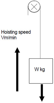 Before selecting the size of a variable frequency drive (VFD), it is necessary to generally know the working environment, the ...
 Before selecting the size of a variable frequency drive (VFD), it is necessary to generally know the working environment, the ...
Single VFD for Multiple Motors
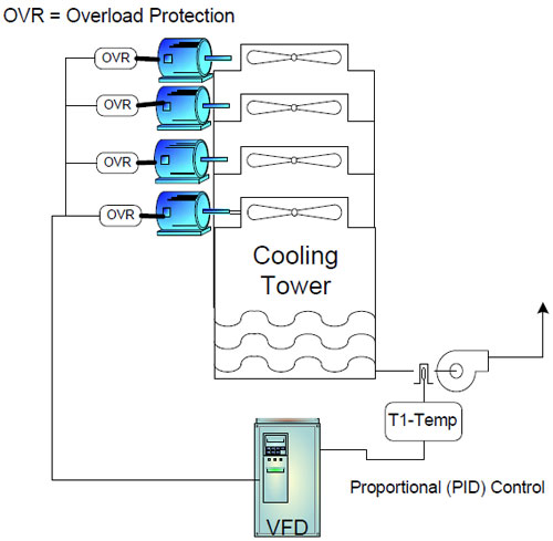 A single variable frequency drive (VFD) may control 2 or 3 motors at a time, multiple motors control is usually done because of ...
 A single variable frequency drive (VFD) may control 2 or 3 motors at a time, multiple motors control is usually done because of ...
PWM Variable Frequency Drive ...
 Pulse Width Modulation (PWM) voltage source variable frequency drives (VFD) presently comprehend the most used equipments to feed ...
 Pulse Width Modulation (PWM) voltage source variable frequency drives (VFD) presently comprehend the most used equipments to feed ...
Variable frequency drive for water ...
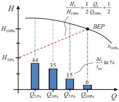 Quantifying the energy efficiency of pump units across markets is a tough task: These units mostly consist of rotodynamic pumps ...
 Quantifying the energy efficiency of pump units across markets is a tough task: These units mostly consist of rotodynamic pumps ...
Variable Frequency Drive Basic Safety ...
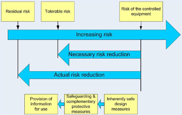 This paper provides guidelines on functional safety considerations when selecting and integrating a variable frequency drive ...
 This paper provides guidelines on functional safety considerations when selecting and integrating a variable frequency drive ...
Variable Frequency Drives control AC motor for energy savings by adjustable speed, for short VFD, also named variable speed drives and frequency inverter.
