VFD Voltage Vector Control
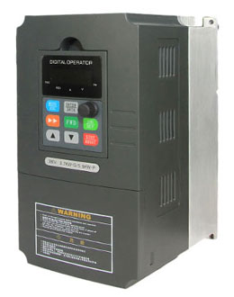
The VFD that I selected and ordered for the control of a standard 1,1kW induction motor in the electric laboratory is from the manufacturer Gozuk. Out of a whole list of VFDs this one seemed the best for future experiments in a practical course about control of electric motors and the simulation of an electric vehicle. The vector control VFD, Gozuk made, is a standard but modern VFD with a lot of opportunities to explore, like open loop and closed loop vector control. The variable frequency drive is developed to control induction motors in an automated environment. This includes that many of the possibilities of the vector variable frequency drive cannot be discovered without additional automation tools to deliver feedback to the vector variable frequency drive. In this paper the connection is made with the theory about VFD.
A first note that can be made is the Gozuk voltage vector control (VVC) principle to get a better approach of output alternating current sine voltage waves. It can be seen as the combination of pulse width modulation and 180°-steering. In this control method each switch of the inverter bridge is kept closed for approximately 60° while the width of the pulses of the other two switches which work at the same time are modulated according a sine wave. In following Figure the potential at point X according to the negative pole is given in time. In the second part the phase voltages ux, uy and uz are given together with the line voltages uL1 L2, uL2 L3 and uL3 L1. By using this control approach the full amplitude of the grid input voltage is available at the output of the VFD while the course of the average output voltage follows a sine function. Because the switch for 60° per 180° doesn't work, the switching losses are decreased.

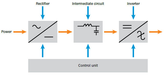
Like shown the variable frequency drive uses a three phase bridge rectifier to convert the input three phase alternating current voltage (3*400V) to a direct current voltage of 565V. After the diode bridge the DC-voltage link is made where after a low pass filter (an inductance in series and a capacitor in parallel) further flatten the rectified voltage. Then the IGBT bridge inverter converts this direct current voltage to alternating current voltage with the wanted amplitude and frequency. Different control principles for the inverter are possible but the default value is voltage vector control, the earlier discussed special vector control method.
A first note that can be made is the Gozuk voltage vector control (VVC) principle to get a better approach of output alternating current sine voltage waves. It can be seen as the combination of pulse width modulation and 180°-steering. In this control method each switch of the inverter bridge is kept closed for approximately 60° while the width of the pulses of the other two switches which work at the same time are modulated according a sine wave. In following Figure the potential at point X according to the negative pole is given in time. In the second part the phase voltages ux, uy and uz are given together with the line voltages uL1 L2, uL2 L3 and uL3 L1. By using this control approach the full amplitude of the grid input voltage is available at the output of the VFD while the course of the average output voltage follows a sine function. Because the switch for 60° per 180° doesn't work, the switching losses are decreased.
Like shown the variable frequency drive uses a three phase bridge rectifier to convert the input three phase alternating current voltage (3*400V) to a direct current voltage of 565V. After the diode bridge the DC-voltage link is made where after a low pass filter (an inductance in series and a capacitor in parallel) further flatten the rectified voltage. Then the IGBT bridge inverter converts this direct current voltage to alternating current voltage with the wanted amplitude and frequency. Different control principles for the inverter are possible but the default value is voltage vector control, the earlier discussed special vector control method.
Post a Comment:
You may also like:
Featured Articles
Variable Frequency Drive Working ...
 This guideline discusses variable frequency drive (VFD) basic working principle and how installing variable frequency drives in ...
This guideline discusses variable frequency drive (VFD) basic working principle and how installing variable frequency drives in ...PWM Variable Frequency Drive ...
 Pulse Width Modulation (PWM) voltage source variable frequency drives (VFD) presently comprehend the most used equipments to feed ...
Pulse Width Modulation (PWM) voltage source variable frequency drives (VFD) presently comprehend the most used equipments to feed ...
Variable Frequency Drives control AC motor for energy savings by adjustable speed, for short VFD, also named variable speed drives and frequency inverter.